My previous blog was about building a flight sim controller using a regular Flysky i6 transmitter. It worked nicely for some time, until one day, the screen suddenly went blank, and it was completely dead...
I checked the regular suspects. The voltage regulators for the processor and the RF module worked fine and everything looked OK. It just would not turn on at all. I was thinking that probably I shorted the 5V coming from the USB port to the 3V3 line on the board for an instant and burned some of the main chips. I gave up on the device and started to build my custom joystic interface electronics and new firmware that read i6's potentiometers as the input to the joystick interface. I was planning to bypass all the electronics of the i6, and use only its sticks (analog voltages of the pots are nicely broken out at the top, just below "CON8").
The day to start wiring it up to the joystick interface. I switched the i6 on out of usual habit. It turned on normally and worked! WTF! Alright, it means intermittent connections. However, it worked only for a short time and went bad again. Such intermittent operation continued from then on. Usual suspect in this case, is bad connections (solder joints, connectors, wires etc.). Looking at the board under a makeshift microscope, the EEPROM chip seemed to have suspicious soldering. I resoldered it. No difference. Then I noticed the top cover of the crystal was bent inwards, as if struck by something. I did not have a 4 pin 5032 SMD package 8MHz crystal laying around, so I unsoldered it and replaced it with a through hole regular crystal. It did work a bit better but still went bad from time to time. When it did work, pressing on the processor package would kill it. But looking at the processor solering, all looked fine.
Eventually, I laid my eyes on the large RF module. I had not given it much thought until then, because in regular RC transmitters, the RF module simply receives input signals from the rest of the circuit. Even if it is broken, the rest of the system would still work. But this one is different; it has bi-directional communication with the processor for setup and running. If it does not cooperate, the processor cannot go further in the program. It had one of the worst soldering job that I have seen on Chinese products (too large for the pick and place machine, it was probably hand soldered). Fairly wide pin spacing, so it was easy to re-solder it. Well, that was the problem. After the re-soldering, it has worked flawlessly since.
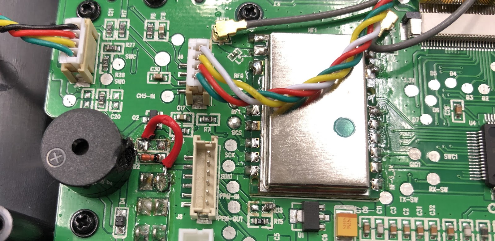 |
| The bad solder joints on the RF module... |
In post-mortem, I understood why it broke. I had removed the PCB from the transmitter to check some of the soldering side traces to the trainer port. However, the PCB is held very tightly in plastic standoffs and requires much force to get it out. The RF module is fairly large and there is no strain relief betwen it and the PCB. So all three conditions must have come together and probably caused some solder connections or their PCB traces to crack. The processor then received no reply from the RF module at startup, and the whole system simply hang.
Now, some rant. There is obviously a reason why these units are so cheap compared to brand name products. It is inevitable that factory reject parts or shady components find their way into them. The plastic or wiring is not the best quality. In this case, the crystal was obviously of dubious quality. I still think that Flysky i6 is exceptionally well made, and if you don't fiddle with it, it will give years of good service. I also think that it is a great platform to tinker with, especially if you do not use it for a critical system, such as a flight simulator.
So there it is. If your Flysky i6 breaks down and goes completely blank at some point, the RF module re-solder is worthy of a repair candidate.
No comments:
Post a Comment