Thursday, April 25, 2013

Ev Yapımı Dört-Rotor

Ev Yapımı Dört-Rotor


Önceki bir yazıda mini dört-rotoru nasıl yaptığımı anlatmıştım. Mini dört-rotorlar yapımı kolay olmasına rağmen küçük parçalar içerdiklerinden mekanik sıkışma, titreşimin giderilmesi ve malzeme seçimi gibi konularda zorluk çıkartabilirler. Bu yazımda yapması ve uçurması daha kolay olacak bir dört-rotor hakkında yazacağım. Amacım kullandığım malzemeleri ve teknikleri anlatmak. Yazıda bahsedeceğim dört-rotor aşağıdaki:

Dört-rotorun genel görünüşü. Verici boyut anlaşılsın diye (1998'den kalma JR X3810 hala çok iyi; üzerinde Corona 2.4GHz modülü var).
Kullandığım parçalar:

Bu dört-rotoru yaparken önce yaklaşık boyuttan başladım. Sıklıkla kullanılan 8x4.5 pervaneler orta boy dört-rotorlarda iyi sonuç veriyor. Ülkemizde de bazı dükkanlarda hem düz hem de ters dönüşlüsünü bulmak mümkün. Bu nedenle onu seçtim. İki pervaneyi yan yana koyunca aralarında yaklaşık 2.5cm mesafe kalması iyi olur diye düşündüm; böylece diyagonalden kol uzunluğu ortaya çıktı. Bunlara karar verince gerisi uygun parçaların seçimi sadece.

Motorlar:  8.x4.5 pervane ile kullanılabilecek motorlar zaten aşağı yukarı belli. Bunlardan nispeten çok alacağımız için fiyatının da uygun olması lazım. Ben bu nedenle bu linkten Turnigy D2822-17 motorları aldım. Biraz internetten arayınca bunların 8x4.5 pervane için uygun olduklarını gördüm. Bu motorların fiyatı fena değil, tanesi 10 Dolar civarında. 4 yerine 5 tane almak iyi olur. Bir arıza çıkarsa yenisini sipariş edip beklemekten iyidir. Bana gelenlerden birisinde sürtünme biraz çok geldi, onu yedeğe ayırdım.

Hız kontrol:  Hız kontrol da yaklaşık motorun azami akımını verebilecek türden ve ucuz olması lazım. Sıkca kullanılan Turnigy Plush markalar var, ama o gunlerde daha ucuza Turnigy'nin tam da çok rotorlular için çıkardığı hız kontrolörler gözüme çarptı. Turnigy Multistar. Bunların 20 amperlikleri işimizi görecektir ve fiyatı da 10 Dolar civarında. Aslında uçuş sırasında yaklaşık 750g ağırlık için sadece 2.5A-3A civarında akım çekiliyor, yani daha küçük sürücü alınabilir ama iki nedenle bunları seçtim: 1. Daha sonra gerekir belki (fiyat akıma göre çok değişmiyor), 2. Uçuş kontrolünce anlık olarak 2.5 Amperin çok üzerinde akımlara ihtiyaç duyulabilir. Yani yüksek kapasiteli hız kontrol daha kararlı uçuş anlamına da gelebilir. Geriye uçuş denetleyici bilgisayar, batarya ve ıvır zıvır kalıyor.

Hız kontrolörünün daha hızlı cevap vermesi için yazılımını değiştirmek mümkün. Bunun için Internette bazı ücretsiz özgür yazılımlar bulunuyor. Ben bunu yapmadan bir uçurmaya karar verdim. Sonuçlar iyi çıktı. Bu sürücülerin yazılımını değiştirmenize gerek yok. Başka hız kontrolörler gibi bunların gaz ayarını yapmaya da gerek yok, bunun bir yolu da yok zaten, aklınızda olsun.

Hız kontrolun bir de BEC çıkışı var. Bunlar 3A olarak yapılmış; oldukça yüksek bir değer. Birbirini yüklememesi için denetleyici bilgisayara hız kontrollardan sadece birinin BEC çıkışını bağlayın, diğerlerinin ya kablosunu kesin, ya da soketten çıkartarak (izole ederek) bir yere bantlayın. Yani dört hız kontrolun sadece birinin kırmızı kablosu denetleyici bilgisayara gidecek, diğer üçününkiler boşta kalacak. Kahverengi ve turuncu kabloları (0V ve sinyal kabloları) ise normal şekilde bağlayın...
 
Motor ve hız kontrolun yakından görünüşü
Denetleyici bilgisayar: Bunun için de çeşitli seçenekler var piyasada. Yeni başlayan ve bilgisayarla arası olmayanlara bunun gibi bir şeyi tavsiye ederim: HobbyKing KK 2.0 Multi Rotor LCD Flight Control Board. Kutudan çıkartıp grafik LCD kullanarak kolayca ayarlayıp uçurmanız mümkün. Ben elimde bulunan biraz daha gelişmiş bir bilgisayarı kullandım:  www.DealExtreme.com Crius Multiwii SE 1.0. Açık kaynak kodlu ve bir çok ayarını kendiniz yapabiliyorsunuz. Yeni başlayanlara zor, biraz bu konuyu bilenlere de büyük kolaylık.
 
Denetleyici bilgisayar ve alıcı. Kontraplak parçanın üzerine monte edilmiş.
Batarya: Tahmini çekilen akımın 10-12A olacağını düşünerek yaklaşık 8-10 dakika uçuş süresi  ve (bolca) batarya rezervi ile birlikte Turnigy Nano-Tech 2.2Ah, 2s, 70C bataryalardan sipariş ettim. Bunlar 180g kadar ve 12 Dolar civarında, yani oldukça ucuz. İşini iyi görüyor. Şimdiye kadar 15-20 kez uçuş yaptım, herhangi bir terslik yok.

Gövde: Bu dört-rotoru hem herkesin yapabileceği şekilde  basit ve ucuz, hem de çeşitli şekillerde imal edilebilir tasarlamak istedim. Gövdenin merkez kısmı 3mm kalınlıkta kontraplaktan, kollar ise et kalınlığı 1mm olan 20mmx10mm aluminyum profilden. Bunu bu sefer yeni öğrendiğim Soliworks ile yapmak istedim. Sonra da ahşap parçaları lazer kesicide kestim. Aluminyum profiller ise elde imal edildi. Tamamlandıktan sonra baktım da aslında 10x10mmlik profiller de kullanılabilirmiş. CAD dosyalarını buradan indirebilirsiniz. Önerdiğim yöntem tahta parçaları lazer ile kestirip aluminyum parçaları da elle hazırlamanız. CAD dosyalarının arasında "CAM_" ile başlayan dosyalar dört-rotorun üzerine takmak için hazırladığım kamera montaj kutusu. Onu da başka bir yazıda anlatacağım.
CAD dosyasından görünüş. Perspektifi yanlış seçtiğim için biraz garip görünüyor.


Nasıl uçuyor? Uçuş videosu aşağıda:

Aslında diğer pek çok dört-rotor videosu gibi sıkıcı, ama düzgün uçtuğunun da kanıtı...

Performans değerleri:

Toplam ağırlık (bataryalı):    710g
Boş ağırlık (bataryasız):       575g
Net kaldırma:                       1445g

Azami güçte gerilim, çekilen akım, güç: 7.7V, 28A, 215W
Dengede uçuş sırasında (710g uçuş ağırlığı): 10.3A (motorlar ucuz ama oldukça verimli)

Toplam maliyet: Kumanda alıcı vericisi hariç yaklaşık 140 USD


Boyut karşılaştırabilmeniz için Gaui 330XS ile birlikte fotografı. Neredeyse tıpatıp aynı (görünüşü o kadar güzel değil tabii).


Alttan görünüş. Eski bir helikopterin iniş takımını araya sünger koyarak çift taraflı bantla yapıştırdım. Ortadan da kablo bağı ile gövdeye sabitledim. Batarya cırt-cırt ile gövdeye yapışıyor ve açılabilir kablo bağı ile de sabitleniyor.


Wednesday, January 9, 2013

Aerial Videos from a Toy Quadrotor

How to Mount a Mini DV Camera to a VL929 Beetle


This post is about how to attach a small video camera to a toy quadrotor. Around 2010, I was tinkering with the idea of building a quadrotor using parts scavenged from cheap coaxial helicopters. They contain a gyroscope, motors, gearing and rotors to use as the powerplants of the quadrotor, small lithium cells etc. So all the ingredients are there. Although the motors are brushed (but coreless), this does not matter much at these sizes, and actually at the low weights the speed controllers required would be prohibitive. The only requirement was to design a controller. 

I was surprised to see quadrotors in the similar configuration introduced to the toy and low end hobby market around the end of the same year. They contain small and abundantly available parts, and therefore are quite cheap. Walkera is a semi-brand in these circles, and recently has been producing fairly good quality models.  Their interesting model is the Ladybird, which uses direct drive DC motors and literally fits in the palm of your hand:


This is very nice and interesting, but around $100 or more, depending on the transmitter that it is shipped with. Also, the tiny direct drive props mean that the extra payload capacity would probably not be sufficient to lift a camera and its battery.

Soon after there were several imitations in the market. One of them, WL Toys V939 is a remarkable copy of the above:
VL Toys 939
It sells for $33.35 at banggood.com, with no transmitter, and about $50 with one, and free shipment worldwide. This is also remarkable. However, it is also direct drive. 

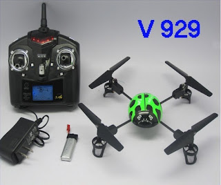
A variant of V939, however deserves some attention, the VL929 Beetle. This is a gear reduction version of the VL939, probably with the same motors, and the same gyro stabilizer. Gear reduction means larger, slower turning props which are more efficient at this regime of flight, and also mean greater load carrying capacity. The gearboxes have ball bearings, and the reviews are quite remarkable. The recent price of $40 including a 4 ch transmitter, cells, charger, spare props and free worldwide shipment meant that overall this looked like a good model! I ordered one and was quite impressed immediately.
VL929 also a Walkera clone. Even the sad insect face was copied...
The transmitter is not of great quality but it is quite sturdy. Actually my only critisisim is that the throttle stick does not have any damping. Also, you cannot get it to mode 3 (Mode 1 for left handed), so I had to open it up and do some soldering.

The model weighs 76g with 1S LiPo cell, and it can lift 134g. This means it has room for 58g of payload. For a keychain camera, this is quite sufficient. Things were looking good. I used a Tigers 600mAh 15C LiPo cell for it, which weighs 15g and costs $12 for 5 of them!

My version of VL929 is a new revision and did not have accelerometers in the controller, and only gyroscopes. I expected some attitude drift and a constant attention to level it. However, there is absolutely no drift and you can fly it all day with no cyclic inputs.

A few words about the camera. This is a generic camera module that records onto SD flash cards, with the model number Mini DV LK-D005

Incredibly with its own removable rechargeable Lithium battery, silicone sheath, simple tripod, belt attachment rig and similar stuff, it costs only about $18. Note that it brags "glass lens" at the front. However, the video is surprisingly good. It weighs 26g with battery, SD card and the plastic case, 15g without the plastic case. A quick check proved that VL929 was capable of lifting it.

So the problem was how to mount it to the VL929. The camera is slightly awkward because of the orientation of the lens. The first trial was to mount it on top of the VL929. After some thinking, I decided to cut off the top of a 500ml water PET bottle, melt some holes at the skirt so that I could fit it over the arms of the gearboxen. On the top where the cap goes, I rolled a paper tube and stuck in the camera, with its plastic case and own battery, together with some sponge to dampen the vibrations:

Camera mounted to the top with water bottle "holder".
This looked rather handsome. Straight off to test fly it. It did lift off well, and it did fly. However, the center of gravity was too high now, and it looked like trying to balance an inverted pendulum. Lots of oscillations and (over) corrections. The resulting video was OK to look at, but not really acceptable. 

The next step was to try to stabilize it by moving the camera to the bottom. In this configuration, surely the low center of gravity would prevent oscillations? Another mount was prepared using the bottom of a PET bottle. A window was cut to insert the camera at one side, and sponge in the center to dampen the vibrations. The camera was held against the sponge with rubber bands. To further "improve" the configuration and bring the center of gravity to the center of the body, I also removed the battery from beneath the VL929, and inserted it in the bottle in the opposite side of the  camera. Four holes at the sides of the bottle allowed it to be attached to the gearbox arms.

Camera looks out its own window and buttons and SD card can be accessed.

The battery at the other side for balance. All pressed against a sponge with rubber bands to suppress vibration.

Close up of camera and bottle attacment holes.


To my surprise, this did not improve stability by much. There was still a lot of wobbling and over corrections on my part. Another great idea into the bin. It was apparent that although the extra weight could be lifted, it was not doing much good for the stability. I had to lower the weitght, and also keep the center of gravity near the center of the model. Removing weight was possible by simply removing the plastic case of the camera (I could have got rid of the camera battery but that meant I would need to re-do the setup each time I connected the model battery which is not convenient; so I kept the camera battery). But how to lower the center of gravity? The angle of the lens made that impossible. When removing the case, I saw that the camera was not rigidly soldered on the PCB, but was actually on a flexible PCB. That meant that the camera could be rotated to any desired angle! This is how I modified the camera:

Camera with the body removed, camera module angled up, and battery fixed with some tape.
The sponge behind the camera module is to reduce vibrations. The camera PCB is not within the field of view. It may look flimsy, but it has worked very nicely for a month. To attach it, I made a shell by cuting out the bottom of a PET bottle, with the usual holes melted through for attachment to the gearbox arms. You can see that above also. The final configuration looks like this:


The camera is attached to the body with two rubber bands. Some paper napkin is between the shell and camera for vibration. It may not be necessary, and I will probably replace it with something better when I have the time. This configuration finally solved the problems of oscillations, and now it flies quite smoothly. Even outside, I could get some decent footage in mild winds. Remember this is a 100g AUW model, so it does get thrown around in even mild wind:


Tuesday, January 8, 2013

Ev Yapımı Mini Dört-rotor (quadrotor)


 Ev Yapımı Mini Dört-rotor (Quadrotor)


Dört-rotorlar 2005 yılı civarından beri oldukça yaygınlaştı. Bunun birkaç önemli nedeni var. En önemlisi mikroelektromekanik sistem (MEMS) cayroskoplar ve ivmeölçerlerin ucuzlaması ve yaygınlaşması. Artık tek kırmık (çip) üzerindeki MEMS cayrolar eksen başına 1TL mertebesinde satınalınabiliyor. İkinci önemli neden kontrol yöntemlerinin basit mikroişlemciler üzerinde uygulamalarının Internet üzerinen açık kaynak kodlu yazılımler olarak dağıtılmaya başlanması. Böylece bir çok insan bunları başka başka sensörler ve rotorlu hava araçları için uyarlamaya başladı. Dört-rotorları yapmak günümüzde oldukça kolaylaşmış olsa da bir tanesini yapmak için gereken parçaları seçmek, karar vermek ve bir araya getirmek yeni başlayanlar için zor olabilir. Bu yazıda kendi yaptığım bir dört-rotoru anlatarak yeni başlayanlara yardımcı olmayı amaçlıyorum.

Genel görünüş. Kalem, boyutun anlaşılması için.

Dört-rotorda kullandığım parçalar şunlar:
  • Pervaneler: 5x5 inç düz ve ters dönen pervaneler
  • Motorlar:  Hextronik 18-11 2000KV
  • Motor sürücü (hız kontrolü): Turnigy Plush 6A
  • Dengeleyici mikrobilgisayar: Crius MultiwiiSE 0.2
  • Batarya: Turnigy Nano-Tech 0.95Ah, 50C
  • Alıcı: CR4D 4 kanallı alıcı
  • Gövde: Tahta çıtalardan, ev yapımı.
Bu dört-rotorun kalışa hazır ağırlığı 180g. ve maksimum kaldırma kapasites de 275g oldu. Parçaları Hobby King (pervane, motor, sürücü, batarya, alıcı) ve DealExtreme'den (dengeleyici bilgisayar) aldım. Toplam yaklaşık 150USD civarında ödedim. Uçuş videosunu aşağıda görebilirsiniz:


Kendisi yapmak isteyenler için bazı notlarım var:
  • Pervaneler: Bu sefer istediğim pervaneleri bulamadığım için 5x5 pervane kullandım. Normalde hatvesi düşük pervaneler dört-rotor için daha uygun, çünkü uçaklardan farklı olarak dört-rotorun hava hızı genelde çok düşük veya sıfır (havada asılı kalma - hover). Bu uygulamalarda büyük çaplı ve düşük hatveli pervaneler daha uygun. Yüksek hava hızlarına çıksaydık, yüksek hatveli pervaneler uygun olurdu. Pervane palini hava içinde ilerleyen bir kanat olarak düşünürsek, düşük hava hızlarında yüksek hatve palin perdövites (stall) olmasına neden olacaktır. Uzun sözün kısası, 5x3 pervaneler daha uygun olacaktı. İlk fırsatta değiştireceğim.
  • Pervanelerin dengelenmesi (balans): Bu da çok önemli. Eğer bir pervane bile balanslı değilse o motorun gücü düşüyor. Dengeyi sağlamak için bilgisayar diğer motorların da gücünü düşürüyor ve aracın uçması zorlaşıyor veya imkansız oluyor. Bu kadar küçük pervaneleri statik olarak dengelemek çok zor olduğundan deneme yanılma yoluyla her motoru çalıştırıp rastgele bir pervane paline seloteyp yapıştırarak titreşimin azalıp azalmadığına baktım. Bu yöntemle oldukça iyi bir denge yakalayabildim. Düz pervanelerin hep aynı palleri hafifti ve 5mm genişliğinde seloteypten 5cm uzunlukta yapıştırmam gerekti (yani çok fazla). Ters pervanelerin balansı iyiydi. Aerodinamik olarak bozar diye endişelendim ama sorun olmadı. Fotoğrafı aşağıda; kaba görünüyor:

  • Motor: Pervane seçimi motoru belirleyecektir. Ancak genel kural olarak nispeten yavaş dönen ve düşük hatveli pervaneler kullanıldığından yaklaşık 1000kV civarında motorlar kullanılması iyi olur. Burada yine istediğim ebatta motor bulamadığımdan 2000kV motor kullandım. Motorun kV değeri 1Volt gerilim uygulandığında motorun boşta yapacağı devir sayısını verir. 2000kV değeri, 2S lityum batarya için 7.4V x 2000=14.800RPM elde ederiz. Motor yük altındayken bunun yaklaşık %20 altında dönmeli, yani yaklaşık 12000RPM. Bunu otomobilin vitesine benzetebiliriz. Eğer bizim motorumuz yüksek hız veriyor ve pervane bu hızda verimli çalışmıyorsa, 5. viteste arabayı kaldırmaya çalışmak gibi bir durum ortaya çıkar. Hem çekilen akım yüksek olur hem de kaldırma kapasitesi düşer. Beğenmesem de bu dört-rotor iyi çalıştı diyebilirim.
  • Motor sürücüler: Motor sürücülerin dört-rotor için özel yapılmış olanları satılıyor. Bunlar normalde saniyede yaklaşık 50 komut yerine 400 komut alabilecek şekilde tasarlanmış. Böylece dengeleyici bilgisayarın hızlı komutlarını daha yakın takip edebiliyorlar. Kontrol açısından dört-rotorumuz ne kadar küçük ve hafifse sık komutlara ihtiyaç o kadar artacaktır. Büyüyüp ağırlaştıkça da saniyede gelen komut sayısının seyrekleşmesi kararlılığa (stabilite) daha az etkileyecektir. Bu dört-rotor küçük olduğundan normal motor sürücünün dengeleme yapamaması ihtimalini düşündüm ama yine de dört-rotorlarda sıkca kullanılan Turnigy Plush markalardan satınaldım. Bunlar hem küçük hem de ucuz. kontrolda ise hiç sorun yaşamadım, çok dengeli uçabiliyor. Videoda görebilirsiniz.
  • Dengeleyici bilgisayar: Bunun seçimi biraz da kişisel tercih. Artık çok düşük fiyata çok çeşitli dengeleyiciler satılıyor. Mesela www.HobbyKing.com adresinde 20-50USD arasında çeşitli tiplerde bulabilirsiniz. Ben kurcalamayı sevdiğimden dolayı içindeki yazılımı değiştirlebilir olanını aldım. Böyle birşey: www.DealExtreme.com Crius Multiwii SE 1.0. Uğraşmak istemeyenler buradan veya başka bir yerden uygun bir tane seçebilirler. Örneğin bu çok ucuz ve iyi görünüyor... Başlangıç için çok pahalı bir dengeleyiciye gerek yok kanımca. Benim kullandıgımda 3 eksende cayro ve ivmeölçerin yanısıra 3 eksende manyetometre (3 boyutlu pusula; her koşulda kutbun yerini gösterir) ve barometrik altimetre de var (irtifayı ölçmek mümkün; böylece irtifa sabitleyici kullanılabiliyor). Ayrıca bütün ölçümleri Bluetooth (telsiz) veya USB (telli) kullanarak gerçek zamanda grafik olarak bilgisayara aktarmak ve aletin ayarlarını değiştirmek mümkün.


  • Batarya: dört-rotorun en ağır parçası olacağından (burada 46g) iyi seçilmesi gerek. Voltajı motorların dönüş hızını, kapasitesi (mAh değeri) uçuş süresini ve deşarj oranı ("C" olarak verilen) bataryadan ne miktarda akım çekebileceğinizi belirler. Öncelikle voltajını belirlemeli. Bu pervanelerin istenen dönüş hızına ve yukarıda belirtilen motor kV hesabına göre seçilebilir. Kapasitesini hesaplamak için örneğin uçuş sırasında çekilen akımlar toplam X Amper ise ve Y dakika uçuş yapmak istersek, kapasite K=XxY/60x1000 mAh olarak hesaplanabilir. Kapasiteyi buldukan sonra da "C" değerini bulmak için C = X/K denklemini kullanabiliriz. "C" için çıkan tam değerde batarya bulma ihtimali az olduğundan bir büyük "C" değerindekini sipariş edebiliriz. Ya da "C" hesabını bir kenara bırakıp en büyük "C" değerine sahip bataryayı ısmarlayabiliriz. Ben ilk önce THK'dan aldığım 25C 2S 800mAh bataryayı kullandım ama bu dayanmadı. Daha sonra yukarıdakini sipariş ettim ve oldukça iyi sonuç aldım.
  • Gövde: Çok rotorlularda gövdenin en önemli özelliği motorları olabildiğince sabit tutmak ve titreşmelerine izin vermemektir. Bunun için hafif ve sertliğin yanısıra burulmasının az olması da önemlidir. Pervanelerin genellikle uzun motorların ucunda olması bu tasarımı zorlaştırır. Büyük araçlarda bu şartları sağlayan en uygun malzeme karbon elyaflı boru, ve burulmayı en aza indiren boru kesiti de dairedir. Ancak anlattığım dört-rotorda buna ihtiyaç yok. Kuvvetler az olduğundan basit tahta çıtalar hem yeterince hafif hem de burulmaya yeterince mukavim. Gereksiz yere karmaşık ve pahalı bir çözüme gerek yok. Kullandıgım gövde 8x8mm 240mm uzunluğundaki iki çıtayı ortalarındaki kalınlığı azaltarak birbirinin üstüne yapıştırarak yapıldı. Ek yerlerine üçgen destekler koydum. Yeterince sağlam. Aşağıda alltan görünüşü var:
Gövdenin alttan görünüşü.
 Bir iki önemli konu: Dengeleyici bilgisayarı yumuşak lastik takozlar üzerine vidalayarak motor titreşimlerinden etkilenmesini azalttım. Alıcıyı yukarıda öne doğru görülen paralel iki yassı çıtanın üzerine seloteyple bağadım (bunlar aslında tahta kahve karıştırıcı). Bataryayı ise gövdenin altına yapıştırdığım cırt-cırta (Velcro) takıyorum. Ek olarak gövdenin altına yapıştırdığım ve ince dikiş ipiyle sabitlediğim yuvarlak iki çubuğa bir tane paket lastiğiyle tutturuyorum (çıtalar aslında bambu kebap şişi). Gövdenin dışına doğru dörtte bir elips şeklinde olan parçalar iniş takımları. Tahta cetvelden (Çin malları dükkanından) lazer kesiciyle kestim. Gövdenin kalkışta tam yatay olması kumandayı kolaylaştırıyor. Bunların öndeki ikisinin üzerine turuncu bant yapıştırdım. Tam arkasından bakınca bunlar görünüyor ve yönünü anlamama yardımcı oluyor (en üstteki resimde). Yapıştırıcı olarak 5dk. epoksi kullandım. Siyanür akrilat (Japon yapıştırıcı) da kullanılabilir ama epoksi eskiden gelen bir alışkanlık. Bu küçük araçta çok az kullanıldığından toplam sadece 2-3g ağırlığa neden oldu. Kullandığım malzeme iptidai gelebilir ancak birkaç önemli ihtiyaca çok iyi cevap veriyor: Birincisi yeterince hafif ve yeterince sağlam. İkincisi ucuz ve üçüncüsü de olması gerektiğinden sağlam değil. Örneğin bataryanın uçuş sırasında aytılıp düşmesi mümkün değil ama kaza olur da bir yere çarparsa kolayca ayrılıyor. Benzeri, alıcı bağlantısı için de geçerli. Böylece kazalarda hasar belirli ve kolay tamir edilir yerlerle sınırlı kalıyor. Bu dört-rotorun belki en özel parçası motor-pervane adaptörü. Bu tornada yapıldı. Pervaneyi vidayla bağlıyoruz, adaptörün çapları pervananin içindeki girintilere tam oturuyor; motor şaftına da set-screw ile tutturuluyor. Oldukça başarılı. Normal adaptör de kullanılabilir tabii.

Bataryayı tutturmak için cırt-cırt ve çıtalara takılan lastik bant. Alıcı ise ince tahta çıtalara seloteyple tutturulmuş.
Uçuşa hazır halde böyle görünüyor.
Pervane adaptörü özel yapıldı.

Başka bir açıdan görünüş.


 Son olarak, bu işe yeni başlayanlara önerim, bundan daha büyük bir tanesini yapmaları, örneğin 8 inçlik pervaneli olanları. Yukarıda anlattığım araç küçük olduğundan iyi uçabilmesi için her parçasının tam çalışması gerekli. daha büyüklerinin biraz daha affedici olduğunu düşünüyorum. Diğer taraftan ne kadar büyük olursa düştüğünde hasar o kadar fazla olabiliyor. Uçurması kolay olsa da model uçurmayı bunlarda öğrenmek pek tavsiye edilmez.

İyi uçuşlar!

Friday, January 4, 2013

Stick and Rudder for flight simulator

Stick and Rudder for flight simulator

Flight simulators are great training aids for getting your private pilot's licence (PPL). However, light aircraft are flown by the seat of the pants they say. Some realism is necessary, especially when it comes to flight controls. I think the most important to master is the rudder control. The joysticks at the shop may be good, but the twist grip for the rudder will not get you far in terms of practice. With that in mind, I built this stick and pedal set in 2010. 
Stick and pedal set general view.
This was designed to be built from readily available materials at the hardware store, plus a few RC model parts. You can build the electronics, or use the internals of an unused PC joystick. Some soldering will be necessary. One note, the pedal set is hinged to the bottom frame, and is not horizontally movable as in the Saitek pro rudder pedals. However, they do work in unison and have stops.

Let me begin with the stick. which looks like this:
The stick. CD is for size comparison.
 The stick is built onto a piece of wood shelving base. At the center is the gimbal assembly. Around the gimbal assembly are the four springs for centering, and in the front are the electronics and the "throttle lever". The grip is from an ancient DK Tronics Joystick for the Sinclair Spectrum. Its push buttons are not wired due to ignorance.


The gimbal assembly, centering springs, electronics and "throttle lever".
Here is the gimbal assembly. I took the trouble to build it with coinciding pitch and roll axes to make it feel "real". However, many aircraft do not have this ideal kinematic setup, and frankly, during use, especially a few minutes into the flight, you would hardly notice the difference. Anyway, the gimbal is built onto a 3mm thick aluminium plate. It was difficult to find small mountable bearings to fit in the small space, so I used industrial ball links sized to fit 5mm threaded rod. This rod was used to build the gimbal axis shafts also. The gimbal is mounted on two short aluminium tubes to the front and back of the stick. 

The potentiometers are mounted on aluminium brackets, which is screwed to the gimbal plate.  Some plastic tubing connects the ends of the gimbal axis shafts and the potentiometers. Make sure to choose fairly hard tubing, because the potentiometers have grease in their bearings to increase the viscous friction. This and a soft tubing means the pots will not respond well to fast stick inputs.  Make sure to select the "A" type potentiometers; the linear kind. The "B" type pots have a nonlinear angle to voltage relationship and are not suitable. Do not worry about the direction of rotation at this stage, it will be adjusted from within the simulator.

The centering mechanism consists of flat springs, attached to the base using corner support angles from the hardware store. They are set at an angle to the pitch and roll axes, but this is only to make it easy to fit. The springs themselves are iron saws, again from the same store, cut in half. Normal spring steel would be quite difficult to cut and drill. However, these saws only have the edges hardened, and softer centers, so they are not too difficult to drill into. They connect to the stick using large RC model rudder horn hardware, including some ball links. I could not find good ball links of the correct size, and those that are installed have some play in them. This is not acceptable, because every time the stick passes through neutral to the other side, you can hear and feel them click.

Finally at the front is mounted the small circuit board for the electronics, a USB PC joystick emulator. It is an open source project RC Joy NG^2. The original project website is nowhere to be found recently, but the ghost of the project can still be seen on the Internet. The board is fully configurable so that you can select which analog inputs are used for which control etc. Obviously the pitch and roll axes are on board. The throttle control is also connected to this with a long cable, and is nothing but a bare potentiometer -"A" type-, a galvanized corner support angle for mounting, and a plastic lever to make it easier to turn. Finally the pedal set is connected to the stick by a connector.

Some detail shots of the gimbal assembly follow:


Close up of the gimbal assembly. You can see how the ball links that support the pitch and roll axes are arranged, the potentiometers and how the potentiometers are connected to the axes.

The "throttle lever". Nothing but a potentiometer and angle support to which a plastic lever is glued.

This shot shows the centering mechanism. The mounting brackets, iron saw "springs" and connecting rods to the stick can also be seen. All from the hardware store and RC shop.

Next let us have a look at the rudder pedal set. The pedals themselves are made of 15mm shelving wood, cut to approximately the size of my feet. They are mounted on the same material wood base using window hinges (those used in plastic window frames) . They are strong enough to take a beating. Galvanized brackets at the bottoms prevent feet from slipping off.

The pedals are connected to a see-saw bar, as seen to the right in the above picture, which is also made of wood. However it rotates on a simple bushing to reduce the friction.


The connection between the pedals and see-saw bar are made with small industrial ball links to take the loads, and hardware store galvanized brackets attach everything together.

Close up of pedal to see-saw bar. The black hex bolt goes through a bushing that is hidden from view and threads straight into the post below.
 The rudder position potentiometer is conveniently attached to the carrier post for the see-saw arm,  and connects to it through a plywood horn and pushrod. This arrangement has some benefits: It is easy to change the ratio, simple to mount the pot, and easy to keep the heavy loads away. I used ball links to avoid play in the mechanism.


 Rudder centering springs are also from the hardware store, along with the galvanized brackets for attachment. There is a subtle twist; I ran ropes through the springs to act as stops. Even if you press hard, the spring will only stretch up to a certain extent. This is especially good during calibration.


 Finally, the whole bunch together. The stick just sits on top of the pedal set with some anti-slip pads. This makes it easier to take apart for storage. Here is a video of it in use with X-Plane 9, (notice the "Attitude Visualizer", the plastic plane in front of the screen which is the subject of the previous postprevious post). The plane in the simulation is, well, a Cessna 172...


 How does it perform? Basically it is good. It fulfills my expectations well. I can now use my feet and get a feel for how they control the airplane. There are a few points worth mentioning for prospective builders though:
  • The range of motion of the stick is small by definition. That means the stick potentiometers turn very little. If I would redesign, I would connect the pots higher up on the stick and connect them like the pedal pot. This will give more motion, and thus better resolution.
  • The centering force is not very large. Near the center the force diminishes. This is inherent from the design of the springs. Hobby shop joysticks use a different (and simpler) mechanism for centering. The same can be said for rudder pedals. Near the center the force is very small, which can cause unintentional slips.


If you are interested in the small model airplane in the video that moves in sync with the simulator, you can find it explained in another blog post of mine, at this link.

Thursday, January 3, 2013

Attitude Visualizer for X-Plane 9 and Linux


I built the attitude visualizer for X-Plane in 2011 as an exercise to learn how to extract real-time data from X-Plane and to control it, especially for my own hardware devices such as physical flight instruments or moving cockpit. X-Plane was made in a way that makes it easy to interface through several ways (explained a bit later). First, a video of how it works. The small plastic airplane in front of the screen follows the roll and pitch attitude of the Cessna 172 that I am flying in X-Plane, in real-time:


As far as hardware goes, it is a general purpose, open source microcomputer board (SUBOARD) with a PIC18F4550 processor, driving two RC servo motors. The reference position for the servos are received from the PC through USB. A plugin was written for X-Plane which acts as a go-between the microcomputer board and X-Plane.

It is quite simple to obtain data from X-Plane 9 or send data to it. This enables you to create  custom hardware or software gadgets that can be used with the program. As an example, I will show you how to read aircraft roll and pitch attitude angles from X-Plane, and send them to a custom built "Attitude Visualizer" which is a mechanical device that rolls and pitches a small, physical airplane model sitting in front of the screen, in real-time, with data streaming from the program. This is a handy device when showing a flight simulator to novices because they may have a difficult time visualizing the attitude of the plane by looking at the cockpit view. This example is on Linux (Ubuntu), however the SDK is very portable, and it is quite straightforward to compile it on other operating systems.

There are several methods to obtain data from X-Plane: Over an Ethernet connection, using data dumped to a text file, or using a plugin. The Ethernet method is great if you want to run X-Plane on several computers at once. The text file metod is good if you also want to log data.

However, if you want to build panels, instruments, or simple devices like the Attitude Visualizer explained here that run on the local computer, then the plugin is probably the most suitable method. The plugin is an extension program that is loaded into X-Plane at startup, and consists of initializer and destructor functions, and functions that are called periodically, at a time interval set by us.

To write a plugin, you must first download the X-Plane Software Development Kit (SDK) from their website. So at this point, please do that first.

Second, download and unzip the source that I wrote (from samples). The source is fairly straightforward, and consists of a few programs:

InputOutput.c: This is the main program, and you would normally only use this. It connects to X-Plane, and using the data structures defined as:
    XPLMDataRef PosnRollRef;
    XPLMDataRef PosnPitcRef;
    char PosRollDesc[40] = {"sim/flightmodel/position/phi"}; //Roll value.
    char PosPitcDesc[40] = {"sim/flightmodel/position/theta"};//Pitch value.
It selects the connection variables within X-Plane. There is no main() function because this is a plugin. The main() resides somewhere within X-Plane. The main functions are:
PLUGIN_API int XPluginStart: Called when the plugin first starts.
PLUGIN_API void XPluginStop: Called when plugin will be stopped.
PLUGIN_API int XPluginEnable: Called if you enable the plugin from within X-Plane
PLUGIN_API void XPluginDisable: Same as above but for disabling.
float InputOutputLoopCB: This is the heart of the matter. This function is called periodically to extract the data. You can then do whatever you like with the data. Here we send it to our USB device (SUBOARD that will command the servo motors to move the physical aircraft model.
int SUBII_Connect: Initializes SUBARD device.
int SUBII_Disconnect: Stops the SUBOARD device.

It is important to note that the function InputOutputLoopCB blocks X-Plane. That means, X-Plane stops while our plugin executes. That also means, if you have a program that blocks (waits for some event to happen, such as USB communications in this example), then X-Plane will wait also. What results is a simulation which will either be slow, or appear like stop motion video. To prevent that, we do the USB communication in another thread, using the "pthreads" library. It is quite simple. By using a separete thread to send the data, the function InputOutputLoopCB simply records the simulator variables to local variables, and immediately exits. Therefore there is no noticeable slow down.

The remaining two functions are specific to our hardware, and would probably be replaced by whatever hardware you may want to use:

sub2usbfunc.c
usblin.c

This is the source code. You should extract it in the SDK root directory. You can compile it using the supplied Makefile, or a simple gcc command (as shown at the top of "InputOutput.c"):

gcc -shared -Wall -D_GNU_SOURCE -o Pitch.xpl InputOutput.c -lGL -lGLU -lusb -I./ -I../SDK/CHeaders/XPLM -I../SDK/CHeaders/Widgets -I/usr/lib/include sub2usbfunc.o usblin.o #(All in one line)

This basically tells GCC to link in the OpenGL libraries (GLU and GL), libusb (for SUBOARD), include the X-Plane SDK files, and also thefunctions necessary for SUBOARD communication.

You should end up with a file named: Pitch.xpl Copy this file into the directory: 
<X-Plane home directory>/Resources/plugins/

That is it. When you next start up X-Plane, you should see your plugin loaded. As supplied, this plugin will not load up if it does not see the SUBOARD connected. However, you can easily modify the program so that it will load in any case. It is also possible to activate/deactivate the plugin from X-Plane menu.

Finally, a bit about  mechanical setup. The overall view is this:

Overview. SUBOARD at lower right, pitch and roll servos lower center, linkages and the plastic plane model at the top.

Another view with pen for size reference.
The linkage consists of a center fixed support with a ball link at the top to act as a universal joint and two pushrods with ball links at the plane side for actuation. Center support is held in place with a screw terminal from an electrical terminal barrier block (generally used in household wiring). A detail view is shown below:

Remember Futaba FP-S 148's?


Here are two shots of the upper mechanical connection. The ball link at the right is for pitch, and the one towards the left is for roll. There is about 45 degrees of travel each way for each axis.


Front lower view. Leftmost ball link for roll, middle for pitch and left for support. I used servo arm pushrod holders to connect parts rigidly together.

This gives you most of what you may need to build the attitude visualizer, except for SUBOARD firmware, and SUBOARD itself. You can build the parts of SUBOARD required for this project on a breadboard by looking at its schematic. The firmware is auite simple, and if there is sufficient interest, I can post the firmware up also.