Friday, May 27, 2016

Connect an SSD1306 OLED display to your STM32F103 board

Oled graphic screens are cheap to get from Chinese suppliers these days. For about 5USD, you can get a 1" sized monochrome display with 128x64 pixel resolution. The connection is also easy because they have I2C interfaces (or SPI; selectable), so only 4 wires, including power is all that's needed.


Display, displaying some text and rounded rectangle courtesy u8glib, ARM port.

STM32F103 is a very nice microcontroller; quite powerful, fast, easy to use, and there are many examples on various applications. This project shows how a popular SSD1306 OLED display can be connected to STM32F103, over I2C port 2, and using u8glib, by olikarus, at: https://github.com/olikraus/u8glib

There are many cheap development boards for the STM32F103 on the Internet, but another source of good development boards is to repurpose existing boards. I used the Naze32 (or one of its clones to be exact, the Flip 32), which come at a price of about US$20. It was designed for quadcopters and thus has many sensors integrated, voltage regulator clock etc. It is a good bargain. The SSD1306 OLED module is already running on Naze32, thanks to CleanFlight control program, and theoretically if you want the same functionality, you can pick out parts from CleanFlight. Unfortunately CleanFlight is quite large, and it was made to support many processors. It is easy to get lost in the source. So I decided to write my own.

The graphics library is u8glib by olikarus. it is hugely popular, but with one significant drawback: It was written for Arduino. There is an ARM port, (the version I used is: u8glib_arm1.18.1), but it requires you to write a few extensions for your particular processor, namely three delay functions, initialization of the connection peripheral, and a function to write to the display. These have been implemented in the files u8g_arm.c and u8g_arm.h. There are many similar samples on the Internet, but there seem to be differences in all, so I had to write them from scratch. Timer 2 is used for the delay functions.


The nice thing about this project is that the display can be easily connected to the board; there are only 4 wires to connect, and they are on matching 2.4mm header pins on the display and the board. Just buy the I2C display and the Flip32, and plug them together. It is therefore mainly a software project, and easy to build. The video shows the simplicity; a battery, the display and NAZE32. It can all be powered from a single LiPo cell (also visible in the video, but not connected), so quite convenient to build portable devices with. A small detail, the red LED flashes show when u8glib is active, so indicate the processor work load.

The sample code displays a few strings on the screen, draws a rounded rectangle around them, and animates them. U8glib allows for many more geometrical shapes and they can be easily inserted in your project with a few commands.
Download the source code at Github.

The project requires that GCC ARM Embedded is installed, together with the ARM port of u8glib and its fonts, as stated above. You should modify the Makefile to specify the respective tool locations. Specifically, the path to u8glib is specified in U8GLIB, and to the fonts directory in U8GFONT variables. How to install and use GCC cross compiler is shown in another blog post of mine.

This project was used as a part of a DIY aviation altimeter, which is at another blog post of minethat you can reach from this link.

Thursday, May 19, 2016

FreeRTOS Simple project for STM32F103 and GCC ARM Embedded


FreeRTOS is a simple way of adding an operating system to your microprocessor projects. It allows you to write more complex programs without worrying about the underlying details. It is quite user friendly and easy to use. However, as with any complex software, there are some details to get just right before it will work as desired. Here I present an example of how two periodic tasks can be created in FreeRTOS. It is intended as a starting point where the basic setup has been completed and working. It is easy to further modify to your own needs. That said, using a RTOS and a multitasking method to accomplish your goals is far from simple, and requires careful design.

Ingredients:
  • GCC ARM EMBEDDED is used, running on a STM32F103RB processor. 
  • The tests were done on a STM32 Nucleo FRB103 board. 
  • FreeRTOS version is V8.2.1, which is recent at the time of writing.
  • It can be built not only using commandline tools, but also the same source codes in a GUI environment such as Eclipse, Keil, Attollic etc. Please remember to modify the Makefile to suit your own directory structure.

The code can be found in my Github pages.

There are some pitfalls in the initial setup of the processor which you must take care of:

1. FreeRTOSConfig.h. It is necessary to set pointers to interrupt handlers to those provided by the FreeRTOS. This is done in the lines:

//Needed for the STM32F10x processors: #define vPortSVCHandler SVC_Handler #define xPortPendSVHandler PendSV_Handler #define xPortSysTickHandler SysTick_Handler

The remaining series of lines in FreeRTOSConfig.h are to set the properties of the processor etc. They are fairly easy to understand.

2. The main body of the program; freertos_testXX.c. This sets up the processor to run the tasks. It is fairly easy to understand and get running, using the FreeRTOS supplied functions. It is necessary to add the line to initialize the nested vectored interrupt controller on the STM32F103:

NVIC_PriorityGroupConfig( NVIC_PriorityGroup_4 ); //Needed for STM32F10x

Sometimes it is necessary to pass a structure to the tasks e.g., to initialize task parameters. An example of that is shown in the last two examples. Task priorities etc. can be set as desired, as documented in the FreeRTOS homepage.

The project is intended to run on a STM32 Nucleo F103RB board. But any similar is fine.

Several versions of freertos_testxx.c have been included. The project can be built using any of them by changing the Makefile. I wrote them when working with the project. Their function is shown below:

freertos_test01.c

First tests of periodic task creation using vTaskDelayUntil. Tasks are created with no passed data structures. Their operation as intended was confirmed.
As set up, T1 and T2 are "periodic" tasks; T2 has lower priority than T1. T2 will only run when T1 is done. T1 flashes the on board LED when it is running. Since T1 has a long execution time, the start of T2 is delayed, and you can see this in the flashing pattern of T2; it is irregular. However, when we exchange the priorities and T2 becomes the high priority task, its flashing becomes regular; whenever it is released, it is immediately executed by the the RTOS kernel.

freertos_test02.c

Same as previous.
Added a single value data passed to the task; its period. The passed value is declared in the function call as a void pointer. In the target function body, it must be either assigned to the correct pointer type (by declaring a pointer of the correct type, and equating it to the function argument void pointer through a suitable type-cast), or each time it is used, type-cast it to the correct pointer type. This may even be done implicitly since the function argument where this is used, or the left hand side of the equality will dictate a correct type-cast. However, better not to leave it to the compiler as implicit; some ambiguity might break the program.
Tasks are also truly periodic (in the sense of FreeRTOS) in which vTaskDelayUntil() function call is used.
It works fine.

freertos_test03.c

Same as previous.
Added a data structure to pass the data to the task. The data structure must be in the memory when the task runs. So that precludes the possibility of creating a data structure on the fly for the task in main() and remove it after task creation. It must be there all the time.
The data structure must be created by using a malloc call (apparently this costs time, but it is done only during initialization, so it is possible).
TODO: Check if malloc is allowed in the heap-1 model.
In this example, T1 parameters are passed using a structure. T2 has only one parameter. This is passed in a simpler manner, by type casting to void * on the fly. Even a literal (directly written number) can be passed in this way.
When created correctly, the data is passed to the task correctly. However, if a normal structure declaration is used within the main function, then apparently, the values are on the stack of main, and are not available to the calling function. The latter method does not work. Program compiles but the tasks do not get the intended values.

freertos_test04.c

Tasks receive all the critical values through the passed variable structure, i.e. period, number of instructions, and GPIO port to toggle for execution. This simplifies the structure for demos, because only 1 task function can be written, and shared among all created tasks.

freertos_test04a.c

Only one task function is written and all tasks are created as different instances of this. Their parameters are set by the passed data structure during the creation function call. This works fine. The body of the same task is called with different arguments to create several tasks.

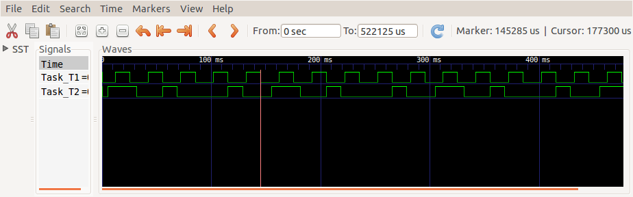
The execution of the tasks can be recorded and visualized using a (cheap) logic analyzer and a viewing program such as GTK Wave, if they set a GPIO pin at entry, and reset it at completion. One sample run of 500ms is shown in the photo below. Task T1 period is 30ms and it has a higher priority. Task T2 period is 50ms and priority is lower at 50ms.

The task execution times seen in GTK Wave
You can see the signals repeat at the least common multiple of the periods (150ms), also called the hyperperiod. You can also see T1 preemts T2 just after zero; T2 seems to execute longer than usual, and T1 and T2 are setting their GPIO pins at the same time. What is actually happening is that when the time to execute T1 comes, T2 is preempted (suspended), and T1 runs instead. This happens three more times in the example above.

You can also see that the execution times of T1 are regular, but the execution times of T2 are irregular. Being lower priority, even if T2 is released, it must first wait for T1 to complete.

Saturday, May 7, 2016

Naze32 Custom Code: Binking Lights with GCC ARM Embedded

Modern flight controllers for drones and RC aircraft make great prototyping boards. At the time of writing, there are STM32F103, STM32F30x and also STM32F4xx based controllers. They are inexpensive, small, include voltage regulators, nice 0.1" header pins, as well as s series of inertial and barometric sensors.

I wanted to build an altimeter for amateur aviation use. At first I wanted to build it on a custom PCB, but then I realized that a flight controller fits the bill nicely, and will come much smaller and cheaper. Because they are widely available, the project can be replicated easily by more amateurs, compared to a custom PCB project

So I took a Flip32 board I had laying around (an exact clone of Naze32 which is quite popular), and decided to port some custom code on it from another similar STM32F103 project for a different board. Schematics are easily found on the Internet. So I found the pin which the LED is connected: Port PB4. Compiled the code, flashed and verified, but... It did not run. What could be the problem?

I looked around, and considered many possibilities, mostly focusing around clock initialization problems. The STM32 series have quite complex clock trees with many different sources of clock and fallback clocks in case one fails. However, after many trials there was no improvement. What could be the problem? I also looked in the source of Cleanflight. It was written for several processors and is divided into many source files, so it is quite difficult to trace the exact startup sequence for STM32F103.

Eventually, looking over the reference manuals (well over 1100 pages), I found the likely suspect. The STM32 has a powerful JTAG interface for debugging which is enabled by default at power-on.  It uses several pins, one of which, PB4 is NJTRST. It is possible to disable the JTAG functionality during the processor initialization, so that PB4 becomes a useable pin again. If you want to be able to use JTAG later on, it is possible to do that anyway, because it is always active after power on. So diabling it here is not a big deal.

You can download the blink source code here. It sets up the processor and blinks the two on-board LEDs in unison. The code itself is simple enough, just another LED blink program. The interesting part is the first few lines of  initialize_PROC() function, where JTAG pins are returned to their GPIO configuration. Programming an ARM STM32F10x processor is described here.

The result is (well, OK, you cannot see it blink in the still shot but...):

Flip32 with blinking lights program. Wire below is from a LiPo cell stuck to the bottom.


I scratched my head a lot over this, so I hope this will help others.


ARM STM32F10x GCC: Connect a volume control encoder

Volume control is nowadays commonly done using rotary encoders rather than traditional potentiometers. They would make nice input devices in DIY projects. This example shows how you can connect such an encoder to STM32F103. As in my other projcts, plain ARM GCC toolsuite is used with no GUI.

Roraty volume encoders output a quadrature signal, and represent the rotation angle and direction using two square wave signals A and B generated in + or  - 90 degree phase shift with respect to each other. They are easy to read in practice; detect the rising edge of signal A, and check the level of signal B; if it is high, encoder is turning in one direction, else in the other direction.

Typical rotary volume encoder.

In real life, it can be a bit more difficult using the cheap encoders which are based on mechanical switch contact. There can be a lot of contact bounce which can be mistaken as switch rotation and poor user experience.

This project shows an example of how such an encoder can be connected to the STM32F103 processor. It reads the encoder and sends '1' or '0' over UART1 as the encoder is turned.

The  source code can be downloaded here. The project is built using GCC ARM Embedded, the installation of which is  shown here. It contains several files to divide  the functionality neatly so that it can be re-used easily. The source also contains Elm-ChaN's xprintf and xuart files which allow using regular printf over serial port, and are greatly helpful in debugging simple applications (but the latency is large and depends on the displayed value).

The encoder device produces a quadrature signal generating two square wave signals which are + or - 90 degrees out of phase depending on the direction of rotation. The signal is decoded using software (not the hardware quadrature counter of STM32F103) because of the low pulse rate. Encoder pins are connected to ordinary GPIO pins. Since many of these encoders come from Chinese manufacturers with low quality, they may have a lot of noise and bounce during rotation. To eliminate this noise, a debounce method is implemented using a DSP lowpass filter (1st order, IIR, 1kHz sampling frequency). The result is nice and smooth action without missing or extra counts.

I built the circuit around a Flip32 flight controller which makes a great STM32 prototyping board. It already has LEDS, 0.1" headers, voltage regulator, USB serial converter and several inertial and barometric sensors. The best is, all of that costs only about $15-20 depending on the configuration. Besides it is nicely compact and easy to carry around. The only gripe is that the Vbat pin is not brought out. Here is a photo of one of the prototypes:

Rotary volume encoder connected to a STM32F103 board, the Flip32 (Naze32 clone).


 I also took a video of operation. The board is connected through a USB-Serial converter to a Linux computer running Kermit. Each time the encoder is pressed and turned, a '1' or '0' is displayed on the screen, depending on the direction. No data is displayed if encoder is turned without pressing (this is a safety feature for the altimeter application this functionality was built for). The press-and-turn can be easily disabled in the source.


To run the program on your board, edit endcoder.h file to change the GPIO pins that are actually used. The SysTick should be set for 1kHz operation and the encoder pins are scanned at each interrupt.

The encoder code was used in another project of mine、aviation altimeter, that you can reach through this link.