Saturday, April 4, 2020

Fly Sky i6 as a flight simulator TX

These days I cannot fly physical RC, so I thought about flying with a simulator. There are very nice simulator software out there. One of the best is Picasim. It has great flight dynamics and graphics. More importantly for me, it can easily run under Linux using wine (give it a try!). Next is the transmitter box. While it is possible to buy a transmitter box for flight sims, they are generally not good quality or offer much configuration.

Looking around the web, I found Fly Sky i6, an entry level transmitter which offers a great number of options. Better still, it is available from China without a receiver or any other accessories, for about $35 including shipment. This is about the same price as "dumb simulator transmitters". The i6 is very interestig because it has a great followers group who are modifying its firmware to make it better. I would have hesitated to use it for a real flying RC model, but when I opened it up for the first time, I was surprised with the good quality. It can be trusted upon to fly simple real RC models.

Back to the topic. One of the most interesting features of the i6 is its "trainer port". It is documented well. The trainer port is a "female mini DIN 4" shape, A.K.A. "S video", and has 5 connections available: GND, PPM OUT, PPM IN, RX, TX. A matching mini DIN 4 male connector looks like this FYI:
Mini DIN 4 male connector (A.K.A. S video)

If you build (see below) or buy a PPM to USB joystick converter module (for around $11), you can immediately use the transmitter straight away. However, there are two "problems" with that! First of all, where is the fun of building if you are simply buying stuff and plugging them together? Secondly, of you buy a sim module, then you will need to run the transmitter on batteries which you must remember to buy replacements or to charge. The purpose of this post is to describe the modifications to the i6 electronics so that you can power it directly from your USB port.

Two modifications are required to the i6:
  1. Modify the trainer port pins so that one of them becomes a power input pin,
  2. Reduce the power consumption so that it will run from the 100mA available from the USB port.

Modification of the tranier port functions

You need to eliminate one of the functions on the trainer port so that you can make room for the power input pin. I selected to eliminate the "PPM IN" pin (of course another can be selected). In essence, all that you need to do is cut the wire to the PPM IN pin from the connector and solder it to the power switch and you would be done for this step.
However, there is a smarter way! The trainer port is connected to the rear case with a cable and a nice connector. It is possible to make a few changes to the components so that the cable is intact. The changes are shown below:
Changes to the PPM IN connection to make it a power supply pin.
I labeled the changes in the photo to match the item numbers below.
  1.  The PPM IN signal goes to connector J8, second pin from top. (The top pin is GND by the way, and the third from top is PPM OUT pin.)
  2. There is a reverse biased protection diode D1 that shorts the PPM IN to 3V3 supply on the board if it exceeds the allowable voltage. Remove that diode. Connect a wire to its left pad (next to the buzzer). This is a bit fiddly because of lack of room and you can see some burn marks on the buzzer. Well, it still "buzzes"...
  3. Connect the other end of the wire to the battery (+) pin. There is actually a more convenient pad for that labeled "BAT+" just to the left of the battery connector.
  4. If you find it difficult to solder to an SMD diode pad, there is also another easy location for the PPM IN pin here.
  5. Finally, you will need to remove the in-line protection resistor R13 that used to connect PPM IN to the processor. I generally lift up one pin and still leave the resistor connected, so that I can take back the changes in the future. In case you need, this is a 1k Ohm resistor.

That is all. Now the "PPM IN" pin on the trainer socket is connected to "battery in" circuit. CAUTION! This has two implications: The USB 5V is now connected directly to the battery box output. If you have batteries in the case, their voltage will be applied to the USB socket of your computer. Always remove batteries from the transmitter before using it. Second; because the USB supply voltage is only 5V, there is no room to use an in-line voltage protection. The i6 starts low voltage alarm when the supply voltage falls to around 4.5V. If you apply a high voltage to this pin (12V or similar) you will burn out the electronics. However, a simple reverse protection is installed, in the form of reverse biased diode D2 across the power supply. I find it good to have batteries installed for a balanced feel. So you may want to install only 3 of the 4 cells, or keep the power connector of the battery box unplugged, or cover one of the cells with tape etc. to keep them all installed. I selected the last option.

Reduction of power consumption

The second item is to reduce the power consumption. The transmitter draws about 100mA with the backlight on. The USB joystick module also requires about 20mA. The total of 120mA is above USB power supply specification and may cause a reset of the USB port on some PCs. The simplest way to reduce power is to remove power to the transmitter module of the i6. However, the microprocessor must communicate with it, and probably will not run without it. If there were a firmware upgrade that disabled the transmitter module, it would have been the best, but I did not come across one. The next biggest load of the i6 is the backlight. It consumes about 20mA and it is simple to disconnect. So that is what I did.
 
All you need to do is cut one trace so that the backlight is disabled. You can also remove R13 but i my case, it was firmly glued down. Anyway, if you want to re-enable the backlight, simply bridge the cut. BTW, the backlight is supplied directly from battery voltage.
 
Cut this trace to disable the backlight.

So, that is all. Now the i6 can be powered directly from USB, and the PPM IN pin has become a power input pin. If needed, it is still useable as a regular transmitter.

FWIW, my Fly Sky i6 PCB is labeled i6-M VER 2.4  20190623


The interface

Finally, the simulator interface (A.K.A the cable) itself. This converts the PPM (Pulse Position Modulation) signal which is standard across most RC transmitters, through the USB interface, into a joystick emulator for the PC. If you look around, there are many candidate projects. If you have an Arduino Leonardo or similar laying around, you can search for such projects. Since I am currently doing development with STM32 series microcontrollers, I had a blue pill board (STM32F103 breakout) laying around and chose to use that. Again, there are many good projects for it especially in Github. I found this one: "STM32-RC-USB-Adapter" by "voroshkov" and did not even bother re-compiling it; used the binary straight from the repo. It worked like a charm. It only supports 4 analog channels. I may in the future upgrade it to 6 all channels if I have time. I have modified the firmware to a contemporary version of MX Cube and added the 5th channel. I will put it up to GitHub later and put a link here. However, there is really no use for an extra analog channel in the simulator. 

The connections to the Blue Pill Board -> i6 are simple. Just buy a mini DIN 4 pin male plug and use that:
  1. GND -> GND
  2. 5V     -> The newly created Power input pin
  3. A8     -> PPM OUT
The photo is below:
The completed PPM to USB joystick adapter

Finally, you need an adjustment. Gamer joysticks have poor gimbals with a lot of electrical noise, so that most OS'es set the default dead zone at the center to a large value and you will not have precise flight control. In your OS remember to calibrate the joystick for good performance. Typically the OS will require that you move the sticks to extremes and then center them while it tries to detect the amount of noise. There is an easier way to calibrate an i6: Manually set each joystick minimum to '0', maximum to '1000', dead zone min and max both to '500' for the best performance.

The setup works well with my 2016 vintage Linux laptop running Ubuntu 16.04 as well as a contemporary Windows 10 machine. There is really no difference to the USB joystick definition across OS'es.

Have fun!

Wednesday, December 5, 2018

SOSS-S8: Simple Open Source Servo STM8S


SOSS-S8 is a DIY servo drive using feedback position control for DC motors with an incremental encoder. It is based on the low cost STM8S103F3 processor with all the functions handled properly by peripherals. Its main puropse is education, by allowing anyone to implement a closed loop position servo using very low cost components and completely open source software tools. You can learn many things with SOSS-S8:
  • Basic concepts in feedback control systems implementation (PID etc),
  • Convert continuous time designs into discrete time (digital control),
  • High precision fixed point math implementation in a tight control loop timing,
  • Writing code for real-time execution and using simple tools to check (LED, cheap logic analyser etc.),
  • Using sdcc, GNU make and standard peripheral library to write a software project for STM8S processor,
  • Simple digital filter implementation,
  • And others...

Currently a textbook PID algorithm is implemented. It is very satisfactory see the motor follow the reference signal, observe overshoot, steady state error, instabilities etc. or tune the control loop using textbook methods like Ziegler Nichols to achieve fast response and zero steady state error. But the real value comes when you connect the SOSS-S8 to your computer and see the control signals on your computer, in real-time, using the excellent SerialPlot software, which is also open source. The development was done in Linux, but it is perfectly valid for Windows or MacOS-X also.

It looks like this...
SOSS-S8 prototype. A PCB may follow someday...

Video here:


Specifications:

  • Control sampling frequency: 2kHz (can be an order of magnitude higher)
  • PWM frequency: 8kHz which is barely audible.
  • PWM resolution at 8kHz: 2000 counts
  • 16bit PID coefficients with 1/32 precision (scaling implemented for speed)
  • Hardware quadrature encoder reading suitable for high resolution encoders (500ppr, 1000ppr etc.)
  • 16 bit control parameters sent in real-time at 500 samples/second for graphing
  • Hardware PWM and timebase generation.
  • Generates its own time based step reference signals, or reads from a potentiometer using ADC.

Hardware:

SOSS-S8 is designed to use very low cost, off the shelf components:
Most of the components are already laying around in a typical workshop, but even if you buy them all, the maximum cost is less than $20. The circuit connections are very simple and can be done on a breadboard using the common "DuPont" patch cables in a few minutes.

I was too lazy to draw a proper schematic, especially since most people will probably be building it on a breadboard. So I drew a connection diagram instead.Next to each module there is a box with the names of connections of that module. Match the names of the connections in the box that is at the other end of the line.

Connection diagram. Match the same pin names at the same position at both ends of the lines.
(Sorry about the raster graphics -JPG- Blogspot does not allow vector graphics...)

How to install and run: Firmware

The firmware source code can be downloaded from my GitHub repository: SOSS-S8. The circuit connections can be found in the file motor.c as comments at the begining of the file. To build the firmware, you need to have sdcc installed as well as STM8S Standard Peripheral Library (one simple modification to the library is needed to make it sdcc compatible), a programmer software for the device programmer and  GNU make. I discuss how to install the development environment, in another blog post. You should test a few simple firmware projects to make sure they work before attempting this one. You can try the timebase project for example. About the only modification to the source is to modify both 'Makefile's, one in the main directory, and the other within 'libs' directory, to tell the compiler your path to the ST libraries. Windows users beware backslash '\' should replace forward slash '/' in the path values! Finally, all you should need to do is:
 $ make flash
and it should automatically compile first the files in the 'libs' folder, produce the local library file 'projectlib.lib', then continue with motor.c, and finally, if SOSS-S8 is connected to your computer, it will be uploaded and ran.

Remember that since this is a control system, the motor rotation direction is important. I took clockwise as viewed from the front of the motor as positive. That means if you apply a positive control signal to the motor, it should rotate in the positive direction, and the measured motor angle must be increasing, otherwise the control loop becomes positive feedback. If either of them are opposite, you should correct them: If the motor turns in the wrong direction, swap its terminals to the power amplifier, or if it turns in the right direction but the encoder reading is decreasing, swap the A and B leads of the encoder. If both are opposite, it will still work, but in the opposite direction to your reference commands. Of course you can also choose counterclockwise as the positive direction.

The communication settings

SOSS-S8 periodically sends measured values over the serial port. Currently it sends the measued motor angle, position reference and control signal at 500 samples/sec. This is quite fast even for the small and fast motor that I used in the prototype. To get the highest sample rate from the microprocessor at a given baud rate, we must minimize the number of bytes that are sent for each sample. The data is packed in the following way:
  • A constant synchronization sequence: 0xAA 0x55,
  • Parameter 1 formatted as 16 bit int, MSB first,
  • Parameter 2, 3, etc. in the same format,
  • No end delimiter or checksum.
For example, using 115200bps, to send 3 measurements, we need to send 8 bytes/sample. That means about 1400 samples/second can be sent, which is quite respectable! Roughly, it should be possible to send about 10 variables at 500 samples/sec before communication speed bottoms out. To add more measurements to the sent data, see the file motor.c. It is trivial; just type-cast the data to 16bit int, separate into two 8 bit u_int's and add them to the print buffer. The rest is taken care of automatically.

SOSS-S8 sends the data in binary form to minimize the processor overhead of formatting and to minimize the amount of data transferred over the serial connection. The serial data transfer is done in a non-blocking fashion: There is a print buffer, a buffer pointer, a message length variable and a "printing in progress" flag. A short code after the control routine periodically checks if the flag is set, and if the UART transmit buffer is empy, puts the next byte out. I did not bother writing a circular buffer for this because of the unnecessary computation overhead of pushing and popping data from the circular buffer. If you need, I have a sample circular buffer, let me know.

Going to the receiving end; we use the excellent program SerialPlot by hyOzd. The measurement data streaming from the serial port of SOSS-S8 in real-time is displayed on the PC. SerialPlot should be configured to synchronize to SOSS-S8 synchronization sequence, and accept int16 values in big endian format. This is configured in the "Data Format" tab of SerialPlot. Do the following settings:

  • "Custom Frame"
  • "Frame Start:" AA 55 (this is taken as hex without 0x prefix).
  • "# Channels:" 3
  • "Frame Size:" Fixed Size: 6 (use 2* # Channels)
  • "Number Type:" int16
  • "Endianness:" Big Endian
  • "Checksum:" unclick enabled.
That's it. Connect your USB-Serial converter, determine the port name (top dropdown list), click "Open" and you should see the motor parameters floating by, similar to an oscilloscope. For best results, adjust the sample size, graph size etc, from the "Plot" tab. I use 2000 samples for a good display. The graph here belongs to the motor shown in the top photo, with a reference that changes repeatedly every second, between 0 and 300 pulses.

You can take a snapshot of the data and save it as a csv file, to be plotted using your preferred graphing software (I like gnuplot, or perhaps Scilab, Octave, Matlab etc.). You can also pause the data, zoom into it and many other things.

Program structure:

The program is made up of the main part in motor.c, and the peripheral drivers in the individual files inside the libs folder. Here I will describe how the peripherals are used. I have first written the code using the functions provided by the STM8 Peripheral Libraries from the manufacturer. However, the code size quickly inflated. I designed the project in several parts (control, communication, timing etc.) and each part on its own quickly reached the ROM size limit. So I re-wrote the code by taking the individual register operations from the libraries and discarded everything else. So the code no longer depends on the library and the ROM size is now under 5kb. If you look at the source code, you will see the original library function calls commented out above their replacements.

Timer 1:

TIM1 is used as the hardware incremental encoder counter. It is initialized in the encoder mode. There is no interrupt associated with TIM1; it is read at control sampling times to calculate the control algorithm. The pins for A, B encoder inputs are PC6 and PC7. To be able to use PC6 and PC7 as TIM1 encoder inputs, it is necessary to program AFR0. To set it up you can write this into the configuration register:

 $ echo "00 00 ff 01 fe 00 ff 00 ff 00 ff" | xxd -r -p > TIM1CH1_Options.bin
 $ stm8flash -c stlinkv2 -p stm8s103f3 -s opt -w TIM1CH1_Options.bin
The associated files are: tim1.c and tim1.h.

Timer 2:

TIM2 is used as the hardware PWM generator for the power amplifier. I used it in asimple way where either TIM2 CH1 or CH2 generate the PWM waveform and the other is kept at ground level. After the calculation of the control signal, the PWM compare registers are adjusted. The PWM frequency is a compromise between frequency and resolution. We want high frequency so that it is not audible but at the same time we want the PWM count limit to be high for high control signal resolution. However their product equals the processor clock frequency. As a reasonable compromise, I selected 8kHz PWM frequency and 2000 count limit. The pins for PWM output are TIM2 CH1: PC5 and CH2: PD3. Again, PC5 can only be used as TIM2 output after the same modification of AFR0 explained above (no need to do anything else). The associated files are: tim2.c and tim2.h.

Timer 4:

TIM4 is used as a timebase interrupt generator. It is a simple 8 bit counter with an inflexible prescaler that can be set only to powers of 2 to divide the processor main clock. I set the prescaler to 1/32 and the count limit to 250 to obtain 2kHz INT. There is a further counter which raises a global flag at every millisecond to generate a ms event for easy timing. The MS event is counted in main() for several jobs. The associated files are: tim4_tbase.c and tbase.h.

ADC 1 CH2:

ADC is used as a reference measurement. A potentiometer can be conected here as a voltage divider. One minor simplification is that a new reading is initiated at the end of control signal calculation rather than at the begining. This is to reduce overhead before control calculation. We use ADC1 CH2 (shared with PC4).

main() triggers the ADC conversion. At EOC (End Of Conversion) an INT is produced. The conversion value is stored in the global variable ADC_RES to be used at the earliest convenience... Conversion is right aligned.

UART:

UART1 transmits variables to a PC. It is initialized to 115200Baud. Some simple string send functions are provided. At the moment, only transmit is used, but command receive methods will be later implemented.

ETC:

This rounds up the more significant peripherals. Of course there is more to it; the clock configuration, GPIO configuration and 7 segment LCD interfaces:

The files clock.c and clock.h manage the clock settings. HSI (High Speed Internal) clock is used and the processor clocked ad 16MHz. It also switches on the peripherals which are needed. The other peripherals are left powered off. Please check clock.c if you want to add more peripherals.

The files gpio.c and gpio.h are used to initialize the GPIO ports (LEDs etc.). Fairly straightforward.

The files HT1621_NoLib.c and HT1621_NoLib.h are for driving the LCD display. I think I had ported them from Arduino library to STM32, and then to STM8 here. The source was further modified to remove dependency on the STM Libraries.

Main function:

Let me explain a little about the main() last but not least. It is in motor.c. It starts typically with the peripheral and variable initializations. Especially the control variables structure ControlValues_t  and EncoderValues_t are initialized. Here the control gains are also set. I wanted a simple way of assigning square wave periodic reference. it is stored in the array references[]

Particularly, the define "ANALOG_REFERENCE" drives the control from ADC. If this is commented out, square wave reference is produced.

The main loop has the following functions:

Check the MS event flag if(MS_TickEventFlag==TRUE) and increment various counters. This makes it simple to generate timed events. For example, the reference value is updated every second.

If the flag for control signal reference is set, the motor encoder is read and motor position is displayed on the LCD.  If analog reference is asserted, first a low pass filter is used to smooth out the voltage reading (most pots are noisy!). The filter is implemented using int manipulation; we shift left, do the arithmetic and shift right 3 times which gives 1/8 precision. Then error calculation is done and control function is called. Finally the next ADC reading is triggered.

If the reference switch time has come if(REF_count>=REF_PERIOD), the next reference value is selected from the array references[].

If the time has come to transmit the next control values to the PC (I call that print): if(PRINT_count>=PRINT_PERIOD), the print buffer is populated. First the synchronization byets 0xAA and 0x55, then the variables are written to the buffer. I typecast the values to int16_t, and then write them to the buffer in big endian format. The printing state variable is also set to TRUE so that the non blocking print routine can send the characters.

Finally the non blocking print routine sends the characters one by one as soon as the UART transmit buffer is empty.

Finaly, the apply_control() function. It calculates the control algorithm and applies it to TIM2 for PWM generation. A simple anti-windup is also performed here. The time spent in the control algorithm can be used to check the processor utilizatin using an oscilloscope. I am hoping to find time to implement other control algorithms for demonstration in this function.


So, go ahead and build yourself a SOSS-S8 and try your hand at closed loop control implementation!

Saturday, September 22, 2018

STM8S time base using SDCC

The standart "hello world" program is usually blinking LEDs. The straightforward way to do this is to use a loop which wastes CPU time. This is simple but imprecise! What to do if we want to blink a LED at, say, 1Hz?

The solution is to use a hardware timer. We set a hardware timer to count from the system clock. If we know the clock rate, then we can calculate the number of counts required. When the timer overflows, we know the predefined time has passed.

We can either keep checking and wait for the timer to overflow, or set an interrupt service routine (ISR) so that it notifies the program of the overflow. Here I demonstrate the latter. A blocking timer function "Delayms" is given. Its argument is the number of milliseconds that the function will block. Non blocking timing is also demonstrated. It uses the signal set by TIM1 overflow ISR.

The above is general knowledge, but my intention here is to show you the details of how the timer (TIM1) is set up for overflow interrupts, how the blocking and non blocking delay can be implemented and how external variables are declared and used (a variable that is set and used by functions in different files).

I also show how multiple-file projects can be implemented in SDCC, with several Makefiles. This project is made up of several files. Some reside in a local directory "libs', others reside in the STM8 provided peripheral libraries. All of the "other" files are first compiled into respective object files (.rel extension), and then stored in a local library built specifically for this project. In this project, the library file is "libs/projectlib.lib". The Makefiles check if "projectlib.lib" is up-to-date and if not, also generate it.

For the source code, see my Github site:
https://github.com/ahmetonat/STM8S-time-base-using-SDCC

To build and flash, type:
$ make flash

For an introduction to STM8 programming in SDCC, see another post of mine.

After building and flashing, you should see the LED blink rapidly for 10 pulses first; this uses the blocking delay function. Then it should settle into a double blink pattern, using the non-blocking metod.


Tuesday, January 2, 2018

Programming STM8S using SDCC and GNU make

Programming STM8S using SDCC and GNU make


Recently I started looking at the STM8 microcontroller from  STMicroelectronics. I have used various microprocessors during the years, from the Z80 around 1990, through Hitachi H8, some TI 320C31~ 320C6711 DSPs, and more recently ARM F1~F4 series. The STM8S sounds like a downgrade, especially since during the time of writing, there is not a great price difference between, say 32 bit ARM F0 and S8, for small scale production or hobby work. 

However, STM8S is an interesting processor. It is simple enough that a newcomer can understand the complete inner workings, while it is a modern processor with great peripherals, especially since the architecture is suitable to be programmed in 'C'. Boards are dirt cheap, I have bought this, with a STM8S103F3P6 board for around $2:

I had also bought a ST-Link V2 programmer clone from China; mine is from DealExtreme.com:
Cheap ST_Link V2 ans SWIM programmer
Cheap and cheerful ST-Link V2 clone!

ST libraries available, but...

ST provides a very nice (and free) standard peripheral 'C' library for initializing and using the on chip peripherals of this processor (V2.2.0 at the time of writing). Using the library, you can very quicky setup and use all of the peripherals of this chip. They have even included some examples for various configurations, making this an even better processor for beginners.

However, there is a catch. The library is only intended to be used wirh proprietary 'C' compilers. That means, you will need to fork out the cash and buy the compiler, or live with code limitations the companies impose with the "free" versions of the compilers. Also, you will need to download quite large installers to start using these toolchains. Perhaps more importantly, you need to register to these companies to be able to download. Which I don't like.

Don't get me wrong, proprietary compiler suites are good for professional work where you need to have a someone to ask questions and expect a minimum performance guarantee with large code spaces and long projects, but probably an overkill for hobby work.

SDCC to the rescue

Small Device C Compiler (SDCC) is a 'C' compiler suite with the GPL licence, supporting many 8 bit microcontrollers. It has recently started support for the S8 processor from V8.4.0V3.4.0. I am using V8.5.0V3.5.0, on Ubuntu Linux 16.04. The basic compiler is provided as well as many components even including a simulator (check the licence of each component, not all are GPL). SDCC can be installed easily in Linux by the command:
$ sudo apt-get install sdcc

Of course GNU make can be used to automate building your code. I like to use emacs as a text editor. With a proper Makefile, it is as quick as using a GUI to develop and debug  your systems. The good side is, nothing is hidden from view in drop down lists in the GUI; they are all in plain view when you edit the Makefile. Also the development environment is very light as it is only a text editor.  BTW, I recommend using Meld to compare files, it is visual, light and very intuitive to use.

So all we need to do is to write a Makefile that will allow us to build S8 code using STM standard peripheral libraries.

All code is in Github

I prepared a sample code that will compile a multi-file 'C' project using SDCC for STM8S processors , which you can download from my Github account. One header file of the STM library must be slightly modified for the library to compile under SDCC (it involves modifying the syntax for inserting inline assembly instructions. This is clearly mentioned in the Github pages.

Please try it out, and let me know if I can improve it!


Wednesday, June 8, 2016

DIY Aviation Altimeter with QNH setting

Aviation use altimeters are extremely sensitive mechanical devices which use a bellows to convert pressure to displacement, and then use a clockwork mechanism to convert the displacement to dial position on the display. Since the overall displacement is quite small (a few millimeters of bellows compression for the ~20,000 ft. altitude range of the device, the mechanism must be fairly complex, precise and maintained periodically. Accurate and sensitive MEMS pressure sensors have been available since around 2005, which are a perfect replacement for the mechanical altimeters. However the early versions were analog (simple Wheatstone bridges) which meant that they were susceptible to drifts, required temperature compensation and fairly complex electronics to read the output voltage with sufficient precision to allow use as an aviation altimeter. 

DIY altimeter.


Technology to the rescue, recently these problems were solved with tiny pressure sensors which include temperature compensation, low drift, and high precision analog digital converters on-board. Simple communication protocol is sufficient to interface with them, and it is only a matter of following the datasheet to implement up to 24 bit pressure and temperature readout. Quite incredible, where the tecnology has come!

One such notable pressure sensor is Measurement Specialities MS5611 series. They have 24 bit precision and high accuracy, with factory calibrated coefficients permanently stored on-chip, which are used to convert raw measurement values to pressure reading. It is a dream come true; such a precision and accuracy is difficult to come by at such low prices, of about $8~10. Better, they come installed in many drone flight controllers. This is great because for about $25, you get a STM32F103 microcontroller with many other sensors, clock, regulator, all broken out to .1" pin headers. A great platform to experiment and develop with (see my blog on using Naze32 for development).

In this project, a full function barometric altimeter for aviation use was implemented using a Flip32 (Naze32 clone) flight controller board with installed MS5611 pressure sensor, an SSD1306 graphic OLED screen on I2C, and a rotary volume encoder. A single LiPo cell powers the system, with about 40mA current draw.

QNH adjustment is also implemented. You can learn the local QNH value of a nearby airport, dial it into the device, and obtain the MSL altitude in feet. In exactly the same way as a conventional altimeter is used. It was compared during flight with the altimeter of a Cessna 172, and the altitude is always within about 50ft, so it works quite well.


It is quite easy if you want to build one! You only need to buy a Naze32 or Flip32, or similar flight controller with a STM32F1, connect the I2C display (only 4 wires), connect the volume encoder (again 4 wires), burn the binary, and you are ready to go! It can be powered off a single LiPo cell. A small 240mAh cell completely hides behind the display, and will power the altimeter for about 6 hours.


Operation: At power up, an information screen is briefly displayed. Then it returns to normal operation where altitude in ft. is displayed in the center of the screen, measured local pressure in hPa and temperature in Deg. C. at the top, and set QNH at the bottom. To adjust QNH, press and turn the dial. The QNH set screen appears. At the center QNH value is displayed and at the top are the MSL altitude in feet and meters. If you know QNH, you can dial it while keeping the dial pressed in, or if you know the MSL altitude, you can dial that, just as in conventional altimeters. Upon releasing the dial, the device returns to the altitude display screen. Double click takes you into the information screen and back out of it.


Information screen at power up.
QNH set screen:  Enter either QNH of nearby airport or known airfield altitude. Turning the knob changes both.

Firmware: The source code of the project can be downloaded here. It uses u8glib graphics library ARM port, and was compiled with GCC ARM Embedded toolchain, easily downloadable from Launchpad. A binary is also provided, if you do not want to compile from source, for direct burning into a Naze32, Flip 32 or similar. Electrical connections are very simple: OLED display connects to the provided I2C terminals (I2C2), encoder to GPIOA: A signal to PA1, B signal to PA3, click signal to PA0. Internal pull ups of STM32 are used for simplicity so no pull up resistors are needed, no smoothing capacitors are needed either, since debounce is done in the software by a digital filter. See my blog posts for u8glib on STM32F103, and on connecting a volume encoder to the STM32F103.

The pressure altitude calculation formula can be found at several places in the Internet. There are a few sets of coefficients with a slight variation. However, the ones used here have been tested aboard a C172, and compare very well with its installed (mechanical) altimeter.

I wrote the pressure sensor communication and pressure calculation routines from the device datasheet.  I also wrote the bulk of u8g_arm.c and u8g_arm.h files using templates from u8g and several examples from around the web. One critical component is the setup of TIM2 for the delays.

So there you have it. Please build one for yourself, and make suggestions on how it should be. I have several ideas in my mind of how to make it better:
  • Implement a menu to adjust parameters (AGL or QNH display, feet or meters etc.).
  • Battery backup or   EEPROM backup for set parameters. Unfortunately flight controllers typically have the battery backup pin of the processor connected to upply voltage. Also, STM32F103 does have self programmable flash but again unfortunately, with a very small cycle count for this application of about 10,000 writes.
  • Upon power up it should default to the latest recorded altitude for best convenience.
  • I have other versions for larger STN LCD displays, for DOGM128W, and for ST7920, both connected over the SPI interface. DOGM128W is nice because it has a small form factor; only the glass panel. But it is somewhat difficult to find. ST7920 is bulkier, but abundant; it is used in the graphical interface of the Reprap Ramps 3D printer user interface, complete with a volume encoder! STN LCD is best in direct sunlight applications. Future blog posts will detail altimeters with those screens.  
Check back here for updates.

Disclaimer: Although this is an altimeter, those who build or use one accept the associated risks and are solely responsible for safe operation. Do not trust your life on it! It is not intended to be a replacement for certified or any other instrument for aircraft (but perhaps a coal stove).


Friday, May 27, 2016

Connect an SSD1306 OLED display to your STM32F103 board

Oled graphic screens are cheap to get from Chinese suppliers these days. For about 5USD, you can get a 1" sized monochrome display with 128x64 pixel resolution. The connection is also easy because they have I2C interfaces (or SPI; selectable), so only 4 wires, including power is all that's needed.


Display, displaying some text and rounded rectangle courtesy u8glib, ARM port.

STM32F103 is a very nice microcontroller; quite powerful, fast, easy to use, and there are many examples on various applications. This project shows how a popular SSD1306 OLED display can be connected to STM32F103, over I2C port 2, and using u8glib, by olikarus, at: https://github.com/olikraus/u8glib

There are many cheap development boards for the STM32F103 on the Internet, but another source of good development boards is to repurpose existing boards. I used the Naze32 (or one of its clones to be exact, the Flip 32), which come at a price of about US$20. It was designed for quadcopters and thus has many sensors integrated, voltage regulator clock etc. It is a good bargain. The SSD1306 OLED module is already running on Naze32, thanks to CleanFlight control program, and theoretically if you want the same functionality, you can pick out parts from CleanFlight. Unfortunately CleanFlight is quite large, and it was made to support many processors. It is easy to get lost in the source. So I decided to write my own.

The graphics library is u8glib by olikarus. it is hugely popular, but with one significant drawback: It was written for Arduino. There is an ARM port, (the version I used is: u8glib_arm1.18.1), but it requires you to write a few extensions for your particular processor, namely three delay functions, initialization of the connection peripheral, and a function to write to the display. These have been implemented in the files u8g_arm.c and u8g_arm.h. There are many similar samples on the Internet, but there seem to be differences in all, so I had to write them from scratch. Timer 2 is used for the delay functions.


The nice thing about this project is that the display can be easily connected to the board; there are only 4 wires to connect, and they are on matching 2.4mm header pins on the display and the board. Just buy the I2C display and the Flip32, and plug them together. It is therefore mainly a software project, and easy to build. The video shows the simplicity; a battery, the display and NAZE32. It can all be powered from a single LiPo cell (also visible in the video, but not connected), so quite convenient to build portable devices with. A small detail, the red LED flashes show when u8glib is active, so indicate the processor work load.

The sample code displays a few strings on the screen, draws a rounded rectangle around them, and animates them. U8glib allows for many more geometrical shapes and they can be easily inserted in your project with a few commands.
Download the source code at Github.

The project requires that GCC ARM Embedded is installed, together with the ARM port of u8glib and its fonts, as stated above. You should modify the Makefile to specify the respective tool locations. Specifically, the path to u8glib is specified in U8GLIB, and to the fonts directory in U8GFONT variables. How to install and use GCC cross compiler is shown in another blog post of mine.

This project was used as a part of a DIY aviation altimeter, which is at another blog post of minethat you can reach from this link.

Thursday, May 19, 2016

FreeRTOS Simple project for STM32F103 and GCC ARM Embedded


FreeRTOS is a simple way of adding an operating system to your microprocessor projects. It allows you to write more complex programs without worrying about the underlying details. It is quite user friendly and easy to use. However, as with any complex software, there are some details to get just right before it will work as desired. Here I present an example of how two periodic tasks can be created in FreeRTOS. It is intended as a starting point where the basic setup has been completed and working. It is easy to further modify to your own needs. That said, using a RTOS and a multitasking method to accomplish your goals is far from simple, and requires careful design.

Ingredients:
  • GCC ARM EMBEDDED is used, running on a STM32F103RB processor. 
  • The tests were done on a STM32 Nucleo FRB103 board. 
  • FreeRTOS version is V8.2.1, which is recent at the time of writing.
  • It can be built not only using commandline tools, but also the same source codes in a GUI environment such as Eclipse, Keil, Attollic etc. Please remember to modify the Makefile to suit your own directory structure.

The code can be found in my Github pages.

There are some pitfalls in the initial setup of the processor which you must take care of:

1. FreeRTOSConfig.h. It is necessary to set pointers to interrupt handlers to those provided by the FreeRTOS. This is done in the lines:

//Needed for the STM32F10x processors: #define vPortSVCHandler SVC_Handler #define xPortPendSVHandler PendSV_Handler #define xPortSysTickHandler SysTick_Handler

The remaining series of lines in FreeRTOSConfig.h are to set the properties of the processor etc. They are fairly easy to understand.

2. The main body of the program; freertos_testXX.c. This sets up the processor to run the tasks. It is fairly easy to understand and get running, using the FreeRTOS supplied functions. It is necessary to add the line to initialize the nested vectored interrupt controller on the STM32F103:

NVIC_PriorityGroupConfig( NVIC_PriorityGroup_4 ); //Needed for STM32F10x

Sometimes it is necessary to pass a structure to the tasks e.g., to initialize task parameters. An example of that is shown in the last two examples. Task priorities etc. can be set as desired, as documented in the FreeRTOS homepage.

The project is intended to run on a STM32 Nucleo F103RB board. But any similar is fine.

Several versions of freertos_testxx.c have been included. The project can be built using any of them by changing the Makefile. I wrote them when working with the project. Their function is shown below:

freertos_test01.c

First tests of periodic task creation using vTaskDelayUntil. Tasks are created with no passed data structures. Their operation as intended was confirmed.
As set up, T1 and T2 are "periodic" tasks; T2 has lower priority than T1. T2 will only run when T1 is done. T1 flashes the on board LED when it is running. Since T1 has a long execution time, the start of T2 is delayed, and you can see this in the flashing pattern of T2; it is irregular. However, when we exchange the priorities and T2 becomes the high priority task, its flashing becomes regular; whenever it is released, it is immediately executed by the the RTOS kernel.

freertos_test02.c

Same as previous.
Added a single value data passed to the task; its period. The passed value is declared in the function call as a void pointer. In the target function body, it must be either assigned to the correct pointer type (by declaring a pointer of the correct type, and equating it to the function argument void pointer through a suitable type-cast), or each time it is used, type-cast it to the correct pointer type. This may even be done implicitly since the function argument where this is used, or the left hand side of the equality will dictate a correct type-cast. However, better not to leave it to the compiler as implicit; some ambiguity might break the program.
Tasks are also truly periodic (in the sense of FreeRTOS) in which vTaskDelayUntil() function call is used.
It works fine.

freertos_test03.c

Same as previous.
Added a data structure to pass the data to the task. The data structure must be in the memory when the task runs. So that precludes the possibility of creating a data structure on the fly for the task in main() and remove it after task creation. It must be there all the time.
The data structure must be created by using a malloc call (apparently this costs time, but it is done only during initialization, so it is possible).
TODO: Check if malloc is allowed in the heap-1 model.
In this example, T1 parameters are passed using a structure. T2 has only one parameter. This is passed in a simpler manner, by type casting to void * on the fly. Even a literal (directly written number) can be passed in this way.
When created correctly, the data is passed to the task correctly. However, if a normal structure declaration is used within the main function, then apparently, the values are on the stack of main, and are not available to the calling function. The latter method does not work. Program compiles but the tasks do not get the intended values.

freertos_test04.c

Tasks receive all the critical values through the passed variable structure, i.e. period, number of instructions, and GPIO port to toggle for execution. This simplifies the structure for demos, because only 1 task function can be written, and shared among all created tasks.

freertos_test04a.c

Only one task function is written and all tasks are created as different instances of this. Their parameters are set by the passed data structure during the creation function call. This works fine. The body of the same task is called with different arguments to create several tasks.

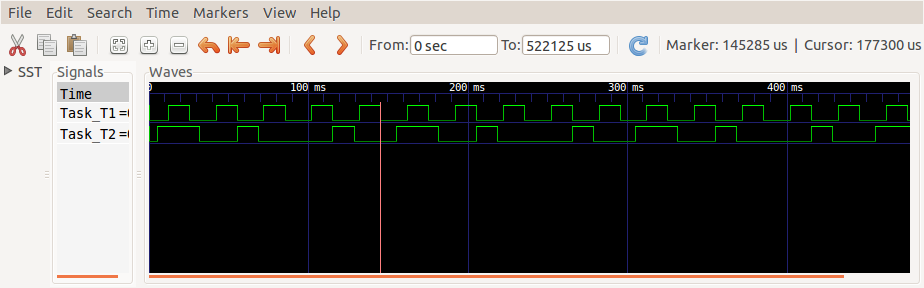
The execution of the tasks can be recorded and visualized using a (cheap) logic analyzer and a viewing program such as GTK Wave, if they set a GPIO pin at entry, and reset it at completion. One sample run of 500ms is shown in the photo below. Task T1 period is 30ms and it has a higher priority. Task T2 period is 50ms and priority is lower at 50ms.

The task execution times seen in GTK Wave
You can see the signals repeat at the least common multiple of the periods (150ms), also called the hyperperiod. You can also see T1 preemts T2 just after zero; T2 seems to execute longer than usual, and T1 and T2 are setting their GPIO pins at the same time. What is actually happening is that when the time to execute T1 comes, T2 is preempted (suspended), and T1 runs instead. This happens three more times in the example above.

You can also see that the execution times of T1 are regular, but the execution times of T2 are irregular. Being lower priority, even if T2 is released, it must first wait for T1 to complete.